JunPus thermal compounds deliver advanced heat dissipation solutions tailored for high-performance AI chips, CPUs, GPUs, and 5G base stations.
Engineered for cutting-edge semiconductor technologies,
our patented thermal pastes optimize thermal conductivity, ensuring stable performance under intensive workloads. Trusted across electronics, data centers, and telecommunications
A practical guide to interface placement, material choice and assembly validation.
AI conceptual illustration of thermal interface options. Not an actual JunPus product, test setup or photograph of a specific semiconductor package. Layer dimensions are illustrative.
In an AI server power supply, a thermal interface material has to fit a specific joint. The available gap, mounting load and electrical requirements determine whether a candidate can make reliable contact between the power device and its cooling surface.
A November 2026 announcement of MOSFETs for AI server power conversion includes dual-side cooling options. [1] Selecting a material for the added top interface still begins with the geometry and requirements of the actual assembly.
Identify the interface before selecting a grade
Dual-side cooling allows heat to leave through the PCB and through a top connection to a heatsink. [2] The two routes have different construction requirements. For an upper cooling surface, the external TIM sits between the package’s designated top cooling surface and the heatsink or cold plate.
The connection from the package to the PCB remains a soldered connection. Do not put ordinary thermal paste or a pad into that solder joint. A separate interface beneath the PCB is relevant only if the design includes a suitable backside cooling surface. Start with the exact package drawing and a cross-section of the assembly.
Choose paste or a pad around the actual gap
A closely fitted joint may suit a thin thermal-paste layer. A larger gap, or variation in component height, may call for a compliant thermal pad or another material designed to fill that space. For dispensing applications, review the tube options described by JunPus and discuss the material, nozzle and equipment requirements with JunPus before choosing a setup. [3]
Treat paste and pads as alternatives to evaluate, not a default stack. Combining them creates an additional interface and changes the assembly. Use a combined construction only with appropriate material guidance and validation. For a pad, review its compression behavior at the intended load. For paste, check the achievable layer thickness, coverage and application process.
Check electrical insulation and mounting load
Confirm the electrical potential of the exposed cooling surface for the exact part. Define the required isolation from the heatsink before choosing the interface. A description such as “electrically non-conductive” does not, by itself, establish a qualified insulation barrier.
Package height variation, surface roughness and heatsink mounting all affect the joint. The package application guidance discusses these issues together with TIM placement and electrical isolation. [4] Keep the package, solder-joint and PCB load limits within the design review. A softer or thicker material should still be checked under the actual assembly conditions.
Compare performance in the assembled power supply
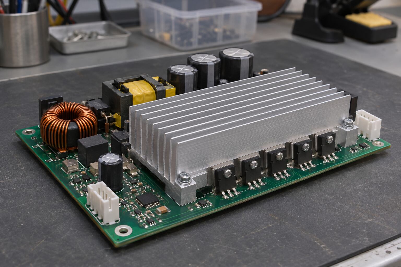
AI conceptual illustration of a generic power supply assembly. Not an actual JunPus product, test setup or photograph of a specific semiconductor package.
A conductivity value in W/m·K helps screen materials, but the contact area, thickness, pressure and measurement method also affect thermal impedance. [5] Ask for thermal resistance or impedance data with the test conditions, then compare candidates using the same assembly procedure.
Set acceptance limits before testing. Record the interface thickness and contact coverage, then measure temperatures under representative loads and cooling conditions. Repeat the agreed checks after thermal or power cycling, including inspection for loss of contact, material movement or excessive compression where relevant. A first temperature reading is a starting point for qualification, not evidence of long-term performance.
Bring the assembly requirements to JunPus
JunPus offers thermal-paste and thermal-pad product categories. [6][7] To discuss materials for evaluation, share the interface drawing, gap tolerance, allowable mounting load, operating temperatures and electrical-insulation requirement. Include the application method and qualification criteria.
Request the current technical data sheet and relevant test data for the proposed grade. Suitability must be confirmed in the actual assembly. The third-party sources cited here explain industry developments and design principles; they do not establish approval of a JunPus material or a partnership.
Contact JunPus with your application requirements to discuss candidate thermal interface materials. [8]
November 3, 2026. These 40 V devices serve low-voltage conversion stages, including secondary-side stages in emerging 800 V architectures. They are not devices for direct connection across an 800 V bus.