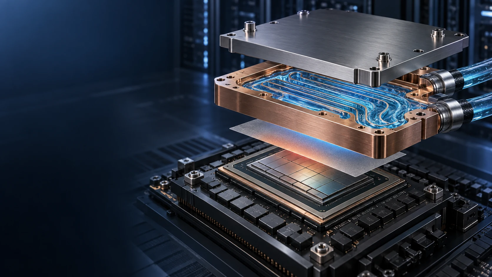
JunPus thermal compounds deliver advanced heat dissipation solutions tailored for high-performance AI chips, CPUs, GPUs, and 5G base stations.
Engineered for cutting-edge semiconductor technologies,
our patented thermal pastes optimize thermal conductivity, ensuring stable performance under intensive workloads. Trusted across electronics, data centers, and telecommunications
A practical guide for SiC and IGBT inverter and UPS designers
A cold plate can be carefully designed and still leave a critical question unanswered: how does heat actually reach it? In an inverter or uninterruptible power supply (UPS), the answer depends on the complete path from the power semiconductor to the cooling system. For a conventional baseplate module, the external thermal interface material (TIM) is the bridge between the module and its heat sink or cold plate. This is the position for evaluating a JunPus TIM against the requirements of the module-to-cooler joint. Selecting that bridge requires more than comparing thermal conductivity numbers.
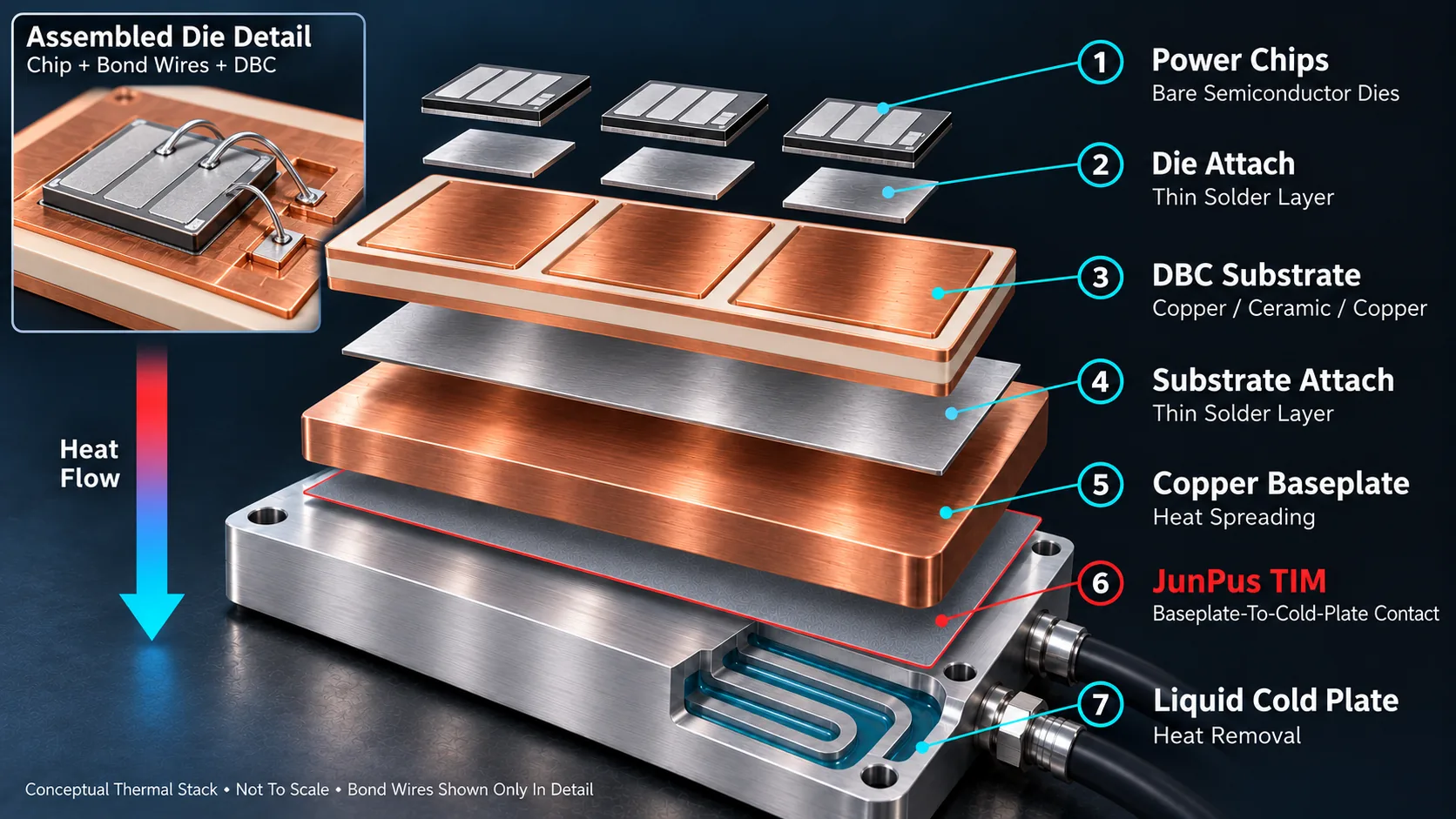
Conceptual thermal stack, not a product cross-section or circuit diagram. Thin layers and separation are exaggerated; simplified bond wires appear only in the detail. JunPus TIM marks the external material-evaluation position, not a specified formulation or thickness.
What recent US and European work tells us
In a presentation dated 2 June 2026, the US National Laboratory of the Rockies (NLR), working with Oak Ridge National Laboratory, identified reliable, low-resistance TIM selection as a remaining challenge in traction-inverter thermal management. The team also cautioned that measured TIM performance does not always match supplier data. Its inverter temperature results are model predictions, not an experimental demonstration. [1]
In Europe, Fraunhofer IZM's 26 February 2026 discussion of power-module packaging emphasizes coordinated design of semiconductors, inductors, capacitors and cooling as power electronics become more compact. [2] For inverter and UPS teams, the practical implication is straightforward: evaluate the interface as part of the assembly, not as an isolated material sample.
Follow the heat through the module
The following map describes a common single-sided, baseplate-cooled architecture. The internal layer order follows the conventional stack in Semikron Danfoss's 2025 application manual; the illustration uses a liquid cold plate as the external cooler. A module manufacturer's actual construction and mounting instructions take precedence. [3, 5]
Component or layer
What it does
Where TIM fits
1 Power chips
SiC MOSFETs or silicon IGBTs generate conduction and switching losses
External grease is not applied to dies inside a finished module
2 Die attach
Bonds the dies to the substrate metallization
The illustrated solder layer is an internal package joint, not external grease
3 DBC substrate
Copper ceramic copper stack carries the circuit and provides designed electrical isolation through the ceramic
Do not confuse this insulation layer with the external TIM
4 Substrate attach
Joins the substrate underside to the baseplate
The illustrated soldered joint is not a grease layer
5 Copper baseplate
Spreads heat and provides a mounting surface
Its underside meets the external TIM in this architecture
6 JunPus TIM
External material evaluation position between the baseplate and cold plate
Select the material form and application process for this specific joint
7 Liquid cold plate
Transfers heat to circulating coolant
Coolant remains in its designed fluid path; it is not thermal paste
Can thermal grease replace package joints above the ceramic
Not as a replacement for their package joints. In this architecture, the power dies sit on the substrate's top copper metallization, rather than directly on bare ceramic. Die attach uses a specified bonding process, such as soldering or sintering, to secure the die and provide its designed thermal and electrical connection. Ordinary thermal grease is nonstructural: it cannot replace that bond or a required electrical interconnect. The substrate-to-baseplate joint is also an internal attachment. The external TIM belongs farther down the stack, between the baseplate and cooler. [5]
Other package architectures exist, but they must not be mixed into this diagram. A Ford-authored SAE paper published on 7 April 2026, for example, examines an epoxy-composite insulating layer applied to a cold plate in place of conventional ceramic substrate arrangements. That is a different package architecture, not a reason to omit a required interface in an existing module. [4]
Thermal contact and electrical insulation are different jobs
In the conventional stack above, the ceramic substrate performs a designed electrical-insulation function. External TIM manages contact between the module and cooler. A grease described as electrically nonconductive is not, by that description alone, a qualified high-voltage insulation barrier. If the system requires isolation at the mounting interface, specify and verify an insulation system for the actual voltage, geometry, environment and lifetime. Do not substitute ordinary grease for it. [3, 5]
Material ingredients are only the starting point
Thermal grease combines a carrier with thermally conductive filler. Silicone and non-silicone carrier systems are available, and filler chemistry and particle distribution vary by formulation. The practical questions are whether the material spreads into the intended joint, remains compatible with its surfaces and retains useful thermal performance over time. A filler name or a headline conductivity value cannot answer all three. [3, 5]
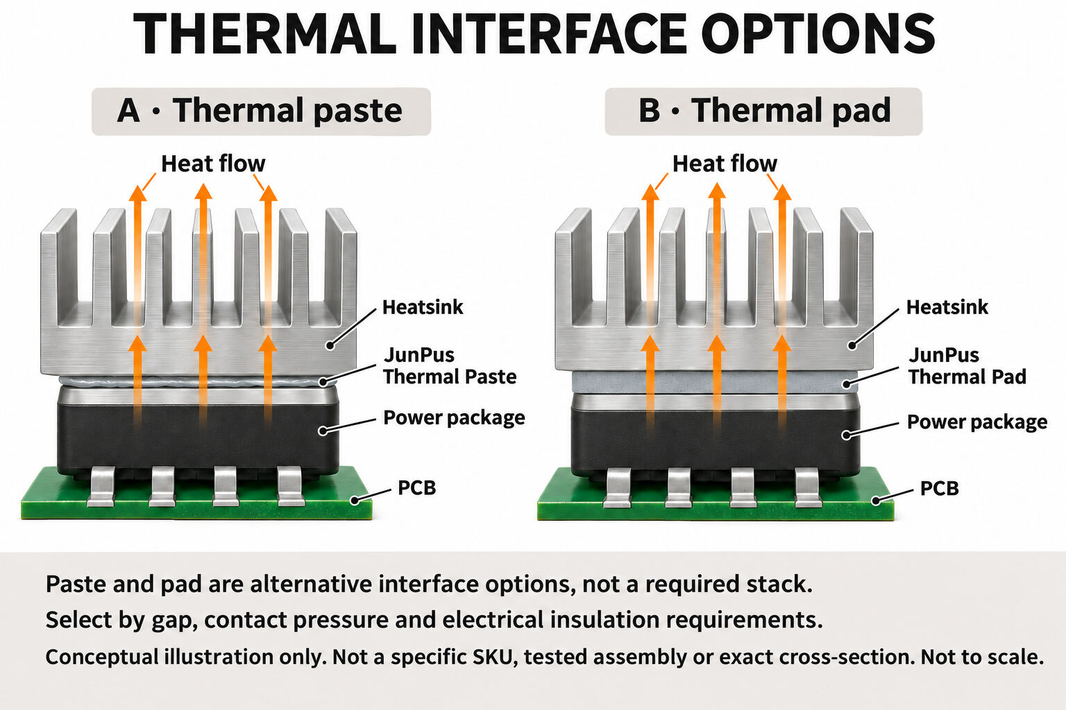
Grease, phase-change material and compressible gap pads are not drop-in equivalents. A close-fitting module joint and a larger component-to-enclosure gap impose different thickness and pressure requirements. Choose the material form around the joint, then verify the result. [5]
Five questions to ask before choosing a TIM
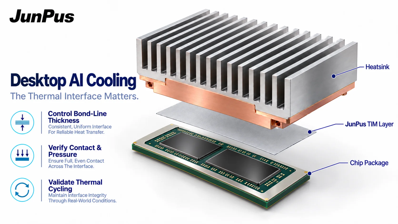
1. What is the actual interface? Record the module part number, contact area, surface materials, flatness and any factory-applied TIM. Follow the module supplier's instructions before adding or changing material.
2. What thickness will exist after assembly? Deposited thickness is not necessarily the final bond line. Control the application pattern and amount; both unfilled gaps and excessive material can undermine the intended heat path.
3. How will mounting be controlled? Define the permitted pressure, fastening sequence and torque from the module instructions. Semikron Danfoss's January 2026 SEMIPACK mounting document illustrates why surface preparation and reproducible application belong in the process specification; its numerical limits are specific to that product family. [7]
4. What happens after cycling? Include temperature cycling, representative loading and inspection for redistribution or deterioration in the evaluation plan. Compare initial and aged thermal behavior, not just a fresh assembly. [3, 6]
5. Which other components need a heat path? DC-link capacitors can require their own thermal connection. NLR's 2026 work separately models capacitor cooling through a TIM and cold plate. Do not assume every capacitor, inductor or control board should receive the same material or clamping load. [1]
A small resistance can matter. As a simplified steady-state illustration, an additional interface resistance of 0.02 K/W carrying 300 W of heat produces a 6°C additional temperature rise across that interface. This is an arithmetic example, not test data. Use the heat passing through the joint, not the converter's rated electrical output, in this calculation.
Bring the joint requirements into the material discussion
For a focused discussion with JunPus, prepare the module drawing or part number, contact-surface details, intended bond line, assembly method, operating-temperature profile and electrical-insulation requirement. These inputs make the next material evaluation more useful than a conductivity-only comparison.
[5] Semikron Danfoss. Application Manual Power Semiconductors. Third edition, 2025. Chapter 3 on packaging and insulation; Figure 3.2.5 on printed page 93; Chapter 5 on cooling and thermal interface materials.
[6] Infineon. XHP2 Power Modules Application and Assembly Note. AN-2024-03, revision 1.10, 2 July 2026. Section 6.1.2 on application-specific thermal and long-term qualification. The filename retains an older revision string; the inspected PDF identifies revision 1.10.