JunPus thermal compounds deliver advanced heat dissipation solutions tailored for high-performance AI chips, CPUs, GPUs, and 5G base stations.
Engineered for cutting-edge semiconductor technologies,
our patented thermal pastes optimize thermal conductivity, ensuring stable performance under intensive workloads. Trusted across electronics, data centers, and telecommunications
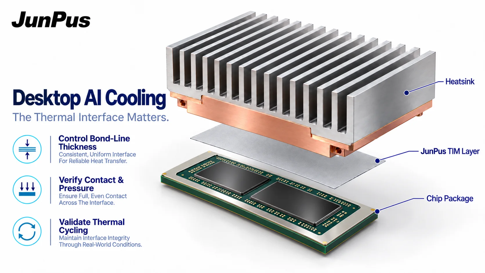
Thermal interface concept. Chip-reference visualization. Not to scale.
Compact AI workstations make thermal-interface engineering a system-level question. The NVIDIA GB10 Grace Blackwell Superchip used in DGX Spark combines CPU and GPU capabilities. MediaTek confirmed its co-design role in October 2025. NVIDIA's hardware guide, updated on 21 October 2026, lists a 20-core Arm CPU, 128 GB of unified memory and a 150 × 150 × 50.5 mm system enclosure. [1][2]
For OEM engineers and thermal-solution teams, the opportunity is not simply to specify a higher conductivity number. It is to qualify the assembled heat path: the component surface, thermal interface material, cooling surface and mechanical mounting conditions. Research on contact pressure, material application and durability helps turn those design requirements into a practical evaluation plan.
Start with the correct heat-load definition
NVIDIA distinguishes the GB10 SoC's 140 W thermal design power from the included 240 W external power supply. The power-supply rating is not the heat load across a single TIM joint, and TDP is not a measurement of every workload. [2] Before specifying material, define the relevant component, operating profile and allowable temperatures. Use the compact CPU-plus-GPU assembly's own power and temperature requirements when defining the evaluation.
This distinction matters commercially: a useful material inquiry needs the interface geometry and assembly conditions, not just the processor name. Cooling performance must be assessed in the intended enclosure and operating environment.
Contact pressure is part of the thermal design
A 2025 IBM Research paper presented at ITherm examined pressure-dependent TIM resistance in a dual-chip package. Its abstract explains that pressure can vary strongly across a die and that assuming a uniform interface resistance can underpredict peak die temperature. [3] For compact AI-system design, the practical implication is to evaluate the interface together with its mounting conditions rather than relying on a single catalogue value.
For a compact-system evaluation, record the mounting arrangement, allowable component loads and resulting bond-line thickness. Do not assume that increasing clamping force is always acceptable. Ask for the material's thermal data at conditions relevant to the assembly, and retain the method, units and surface conditions with the results. Differences between samples should not be attributed to material formulation until assembly differences are controlled.
Qualify the deposited material and the assembled joint
A 2024 study by researchers at Karlsruhe Institute of Technology and Bosch investigated automated TIM dispense-path planning, including experimental validation on automotive production equipment. The work addressed coverage, trapped air, overflow and manufacturing constraints. [4] For engineers developing a compact AI assembly, this work provides a useful process principle: evaluate the dispense pattern and the final interface together.
For a thermal-paste trial, document the applied quantity, pattern, joining procedure and final coverage. Check the agreed criteria for voids and material migration into sensitive areas. A visually tidy deposit is useful process evidence, but is not by itself proof of a satisfactory thermal joint.
Look beyond the first temperature result
Initial thermal performance and durability answer different questions. Foundational U.S. national-laboratory research measured bulk and contact resistance of thermal greases and monitored degradation associated with pump-out and dry-out during accelerated cycling. [5] This work provides a useful foundation for comparing initial thermal performance with the interface condition after cycling.
An evaluation plan should compare the initial condition with agreed thermal or power-cycling checkpoints, using a repeatable assembly and measurement method. Define the operating range, inspection method and acceptance limits before testing. Report changes in thermal resistance and interface condition rather than promising a universal service life.
Turn the heat-path review into a JunPus material inquiry
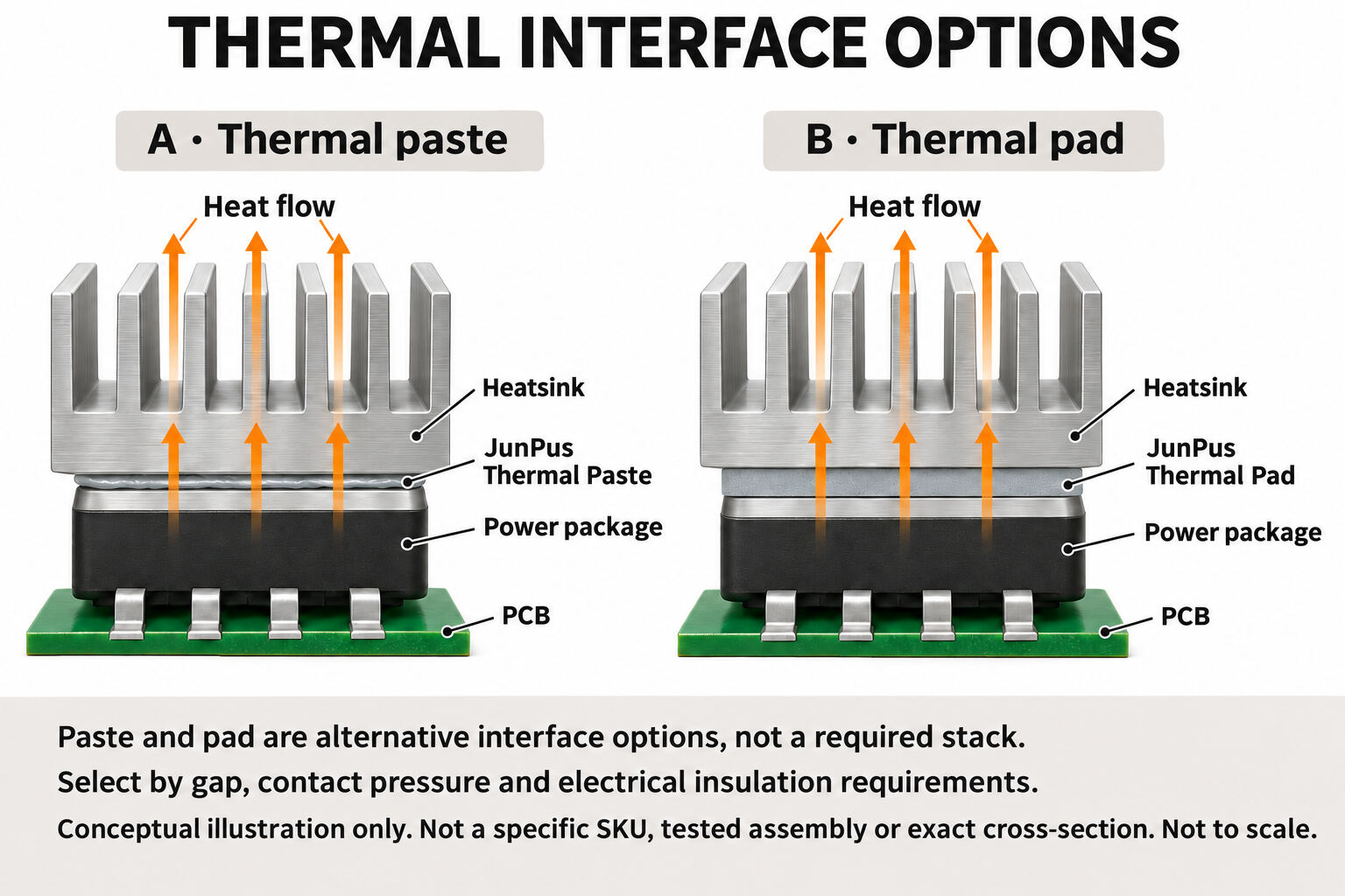
JunPus lists thermal-paste and thermal-pad product categories. [6] The next step is to identify the actual joint and request a suitable candidate for evaluation, not to assume that paste and gap-filling pads are interchangeable. Ask JunPus to review:
The component and cooling-surface geometry, including the intended interface location.
Target or measured bond-line thickness, gap tolerances and allowable mounting load.
Surface materials, operating temperatures and workload profile.
Application method, production requirements and electrical-insulation needs.
Baseline material, test method, qualification criteria and required documents.
For JP-DX1, JP-DX2 or JP-DXSquare Elite inquiries, request the applicable current TDS and test conditions before selecting a grade. Build the evaluation around the selected grade, the actual assembly and agreed thermal and reliability targets.
Planning a compact AI-system thermal interface? Send JunPus your assembly requirements and evaluation criteria to discuss candidate materials and the evidence needed for your project.